


- introduction
- Installation and connection
- configuration
- Global phone book
- Firmware update
- Settings web interface

introduction #
In a typical telephony facility, the M-Series base station is connected to the local area network (LAN), which in turn is connected to a telephone system or a VoIP or IP service provider. The base station converts the IP protocol into the DECT protocol and forwards phone calls to and from the mobile devices.
In order to be able to use the DECT telephones of the M series, the base station must be connected to your LAN and the handsets must be registered on the base station. These instructions describe the manual configuration of a base station.
- Information on multi-cell operation (M700 only) can be found in the "Multicell Deployment Guide Snom 700" http://wiki.snom.com/Snom_M700/Documentation.
- Information on provisioning can be found here: "Provisioning Guide M700 and M300 Base Stations"http://wiki.snom.com/Snom_M700/Documentation.
The configuration and management of the M series base stations correspond to most of the configuration and management files used by Snom. We recommend a local HTTP / HTTPS server for firmware updates, central administration of settings and hosting of firmware files for base stations, handsets and repeaters. The updates of handsets and repeaters are done wirelessly from the base station.
The base station is normally initialized completely automatically via DHCP. If the base station cannot find a DHCP server in the subnet, you can set it up manually via your web browser. You have to enter at least the IP address, the network mask, the IP gateway and the DNS server. Further information that may be required depends on the specifications of your VoIP or IP service provider or your local network; please inquire about this with your provider and / or your network administrator
Installation and connection #
M.700
Power supply #
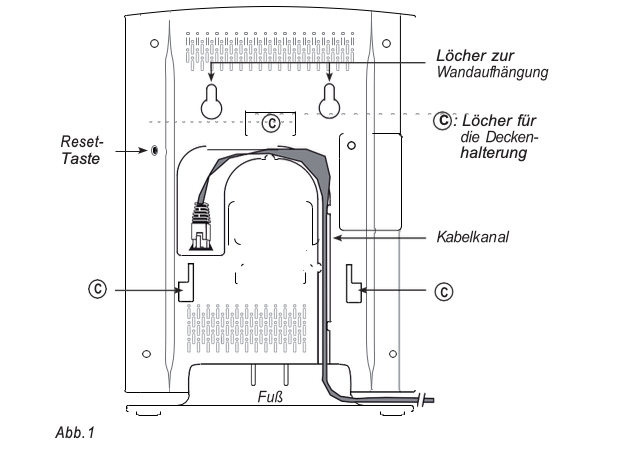
The M700 is powered and networked via PoE (Power over Ethernet). The PoE cable is connected to the RJ45 socket on the rear of the device (see Fig. 1, below). There is no connection option for a power supply unit.
Note: If your network does not offer PoE, you can connect a PoE injector as a midspan device for power supply.
Lineup #
The M700 is supplied with a fixed base for installation on a desk, shelf, floor, etc. Without the base, it can be mounted on the wall or under the ceiling.
Note: The separately available ceiling bracket, product number 00003933, is required for ceiling mounting. It can also be used to securely screw the device to the wall instead of hanging it on screws or hooks.
Standing arrangement #
- Connect the Ethernet cable to the RJ45 socket on the back of the device (see Fig. 1).
- Place the cable in the cable duct.
Attachment to the ceiling or wall #
The M700 can be mounted on the ceiling or on the wall.
Before mounting it on the ceiling or wall, you must remove the foot and connect the Ethernet cable to the device.
- Press the tab (Fig. 2, arrow 1) on the foot inwards and at the same time pull the foot away from the housing
(Arrow 2).
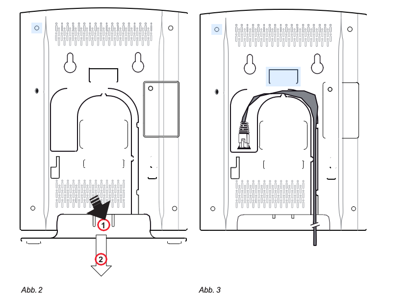
- Insert the plug of the Ethernet cable into the RJ45 socket on the back of the device (Fig. 3, above).
- Fix the cable in the cable guide (Fig. 3).
Wall mounting
There are two holes on the back of the M700 (see Fig. 1 on page 13) that can be used to hang the device on the wall using two screws or hooks.
Note: Screws / hooks and dowels are not included in the scope of delivery. Use screws or hooks and dowels suitable for your walls.
The separately available ceiling bracket, item no. 00003933, can be used to screw the M700 permanently to the wall.
- Mark the centers of the two holes on the wall. The center points should be horizontally 60 mm apart.
- Drill the holes and insert the dowels.
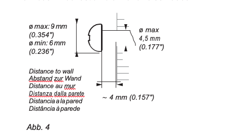
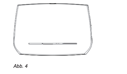
- Screw in the screws (screw size and fastening see Fig. 4).
- Hang the device with the two holes at the top on the back of the device (see Fig. 1Page 11) on the screws.
- Gently pull the device down until the screws click into place.
Attachment to the ceiling
Note: use always the separately available ceiling bracket, item no. 00003933 to mount the M700 on the ceiling.
Do not attempt to mount the device on the ceiling without the bracket. The device will fall down!
- Screw the ceiling bracket to the ceiling using the four dowels and screws included in the scope of delivery.
- Remove the base of the M700 (see Fig. 2) page 11).
- Connect the Ethernet cable to the RJ45 socket on the back of the device and fix the cable in the cable guide (see Fig. 3 on page 11).
- Position the M700 under the bracket so that the three holes / recesses marked with (see Fig. 1 Page 11) located directly under the three hooks on the ceiling bracket.
- Push the M700 up so the hooks are in the holes.
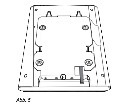
- Push the M700 in the direction of the right-angled "foot" of the ceiling bracket, marked in Fig. 5, until the two lugs at the bottom of the M700 (see Fig. 3) open Page 12) peek out of the two middle holes of the "foot" and the M700 audibly clicks into place on the ceiling bracket.
User interface of the device #
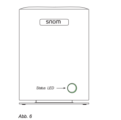
LED status display #
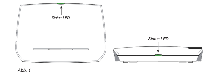
There is a multi-colored LED display on the front of the device, which shows the current operating status of the device (Fig. 6). After the PoE cable (or the cable of the PoE injector, if PoE is not available) has been connected to the device, the orange LEDs of the LED display start to flash. As soon as the LED display lights up green, the device is connected to the network and ready for use.
LED color operating status
Solid green Ready for use
Flashing orange Device is starting up
Flashing red Connection to the network or registration failed Off No power supply
Green, flashing quickly Software update is in progress
Reset button #
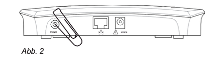
The reset button on the back (Fig. 1 on Page 11) is used to reset the device to the delivery state. To initiate the reset, press the button with an object such as the end of a paper clip for about 10 seconds.
M.300
Power is supplied via the included power supply unit.
installation #
The M300 can be placed on a desk, shelf, or other flat surface, or hung on the wall.
Installation on a level surface #
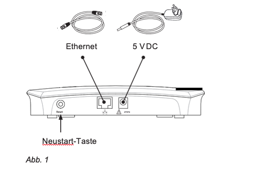
- Connect the Ethernet cable to the RJ45 socket on the back of the device (Fig. 1).
- Connect the barrel connector (DC plug) of the power supply unit to the 5V DC socket on the rear of the device (Fig. 1).
Wall mounting #
For wall mounting, the M300 is simply hung on two suitable screws or hooks.
Note: Screws / hooks and dowels are not included in the scope of delivery. Use screws or hooks and dowels suitable for your walls.
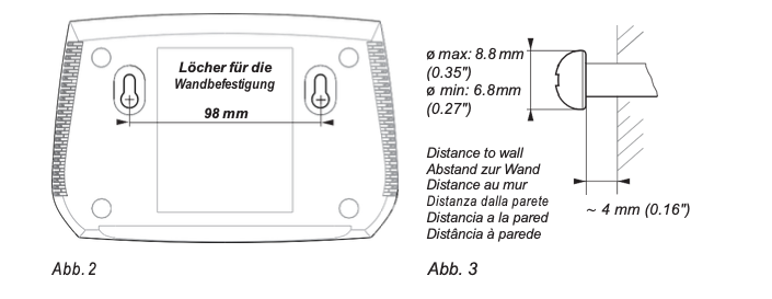
Mark the centers of the two holes on the wall. The center points should be 98 mm apart horizontally (Fig. 2, above).
Note: If the device is hung on the wall, the sockets for connecting the Ethernet cable and power supply are at the bottom of the device (Fig. 4). We therefore recommend installing the device above the Ethernet connection and the electrical wall socket.
- Drill the holes and insert the dowels.
- Screw in the screws (screw size and fastening see Fig. 3, above).
- Hang the two holes (see Fig. 2, above) on the back of the device on the screws so that the LED on the device faces up and the connections are below.
- Gently pull the device down until the screws click into place.
- Connect the Ethernet cable to the RJ45 socket on the bottom of the device.
- Connect the barrel connector of the power supply unit to the 5V DC socket at the bottom of the device.
User interface of the device #
LED status display #
The multi-colored LED display is located on the front or on top of the device, depending on whether the device is hanging on the wall or on a flat surface (Fig. 1). After the device has been connected to the power supply and the network, the orange LEDs start to flash. As soon as the display changes to a constant green, the network connection is established and the device is ready for use.
LED color operating status
Solid green Ready for use
Orange, flashing Device is starting up (booting)
Flashing red Connection to the network or registration failed Off No power supply
Green, flashing quickly Software update is in progress
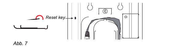
Reset button #
The reset button on the back / underside of the device (see Fig. 2) is used to reset the device to the delivery state. To reset the device, press the button with your fingernail or something like a paper clip for about 10 seconds.
configuration #
In order to be able to use the DECT telephones of the M series, the base station must be connected to the telephone system in your network or to your IP provider and the handsets must be registered on the base station.
Information about the provisioning settings can be found in the "Provisioning Guide M700 and M300Base Stations" http://wiki.snom.com/Snom_M700/Documentation.
Information about multicell operation (M700 only) can be found in the “Multicell Deployment Guide Snom 700” http://wiki.snom.com/Snom_M700/Documentation.
The M-series base stations follow most of Snom's setting and management schemes. For firmware updates, central setting management and hosting of firmware files for base stations, handsets and repeaters, we recommend a local HTTP / HTTPS server. The handsets and repeaters receive updates via radio from the base station.
Preparatory actions #
In most cases, your phone will initialize automatically. If the phone does not detect a DHCP server in the subnet, you can set it up manually in its web browser. You will at least need to enter the IP address, IP gateway and DNS server. If your IP provider or your network needs further data, ask your provider or your network administrator about it.
Find the IP address of the base station #
You can use any M65, M85 or M25 handset that is near the base station. The handset does not have to be registered on the base station.
- Connect the base station to your network and wait for the LEDs to turn green.
Press the menu button

of the M65 / M85 or on the center of the navigation key at
M25. The main menu appears on the display (Fig. 1).
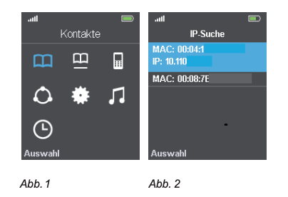
Enter * 47 * (asterisk 47 asterisk) on the keyboard. The screen IP search opens (Fig. 2). If your handset has found more than one base station, look at the MAC address on the type plate on the back of your base station and use the navigation button to select the relevant device on the handset display.
Open the device's web browser #
- Open a browser on your PC. Enter "http: //" and the phone's IP address in the address line, e.g. http://192.168.10.115, and press the ENTER button. The authentication window opens.
- Enter the username and password. The default for both is admin:
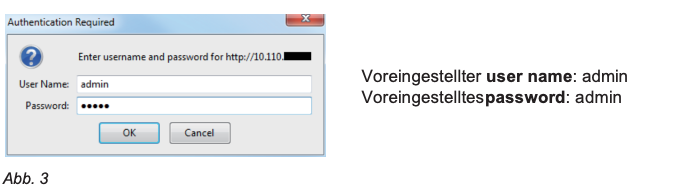
- click on OKto confirm your entry.
The page Home / Status opens with the system information. The vertical menu on the left side of the window always looks the same, no matter which window is currently open. Click on a menu item to open the associated window.
Initial settings #
server #
The default settings are automatically adopted during the initialization. The description of the settings can be found in the section "Server" on page 56.
Language, country, time / date #
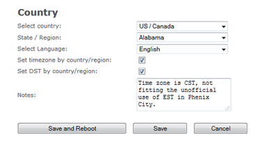
The page Country settings Contains pull-down menus from which you can select your country and, if available, a federal state or region in this country, as well as the language in which the pages of the base station's web browser are to be displayed.
There are also two check boxes for the settings Use the time zone of the country / region and Use daylight saving time in the country / region. Both are checked by default,
ie selected. This means that the time zone and daylight saving time settings of the selected country and, if applicable. of the state or region are automatically adopted.
Select country, region and language
- Choose yours country from the pull-down menu.
If you have selected a country such as the USA or Australia, in which there are several time zones, the pull-down menu with the respective states or regions is available. This submenu does not exist for countries with a single time zone.
- Choose the language for the web browser pages of the device. The default setting is English; the language can be set regardless of the selected country.
- If you want to set a different time zone than that of the country set in step 1, click the highlighted check box of Use the time zone of the country / regionto remove the checkmark and turn off the automatic setting.
If you do not want to use daylight saving time, click the check box of
Use daylight saving time in the country / regionto remove the check mark.
Note: Clicking the check boxes on the page Country settings leads to the setting and removal of ticks on this page as well as on the page Time settings.
If the respective automatic setting is removed, the settings of the time zone or Daylight saving time manually on the page Time settings be made.
- click on to save.
Extensions - M700 #
In order to be able to use a handset, an extension must be set up on the base station and the handset must be registered for this extension on the base station; there are two methods of registration. The extensions (or accounts) specified in the
German language version user correspond to the "identities" that you know from the corded Snom telephones.
Note:
- An extension / identity can only be registered by one handset in your DECT system, regardless of whether it is a system with a single base station or a multi-cell system with several base stations. Do not try to register more than one handset to an extension / identity.
- On each handset you can only one extension / identity per SIP server set up, regardless of whether it is a server in your local network or an external server, e.g. with an IP provider.
Setting up extensions - M700 #
- In the menu on the left, click userto open the page.
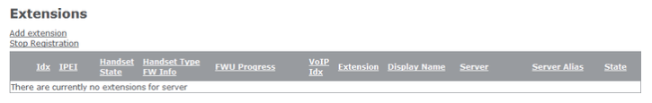
- click on add user.
The information required may vary depending on the requirements of your telephone system. In any case, it is necessary to select the Handsets (New Handset or Handset Idx 1, 2, 3 etc.), SIP user (Number of the extension) and the selection of the SIP servers on which this extension is set up. The other settings depend on the requirements of your telephone system or IP provider and can, if not required, remain empty. Please ask your IT administrator or IP provider. Required settings:
- Handset. The default is New handset (new handset). You can select an existing handset IDx in the pull-down menu.
- Enter the extension number in the From text field SIP user a.
Note: If the number of the extension is also the number of the mailbox of this extension, enter it in the text field of Remote inquiry number, and, if no name has been configured for the mailbox, also in the text field from MWI number a.
If a PIN is required to listen to the mailbox, enter it in the From text box pin code
a.
Note: You can obtain this PIN from your IT administrator or IP provider. It is not the handset PIN that is required to reset the handset and / or de-register it from the base station, nor is it the access code (AC code) that you need to enter to register the handset on the base station .
- Select the server in the pull-down menu from server out.
click on to save.
Registering the handset on the M700 - method 1 #
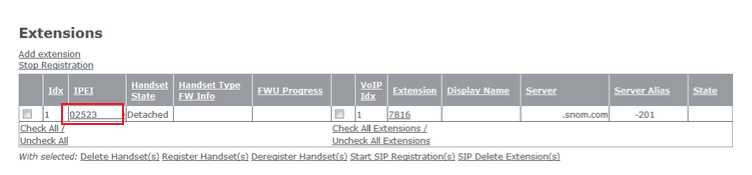
- After you have set up the extension - as described in the previous section - click in the table on the page user on the row of capital Fs in the column IPEI.
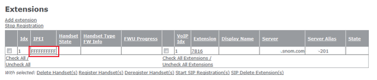
Enter the IPEI of the handset in the handset window.
Note: To find the IPEI (International Portable Equipment Identifier), open the menuSettings of the handset, select status and scroll to the Telephone status down, at the end of which you will find the IPEI. The IPEI consists of a sequence of 10 characters, which can be digits or capital letters. Leave out the colons that divide the characters into groups of two.
- click on to save. In the table on the user-Page you will see the IPEI in the column IPEI was entered.
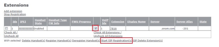
- Click the box to the left of the Idx and then on Register handset (s).
Click the box to the left of the VoIP Idx and then on Start SIP registration (s).
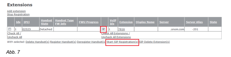
The handset is registered to use the extension.
Note: To use the handset it is also necessary to activate it via the handset menu (Settings -> connection -> To register) to register at the base station. For more information, please refer to the handset operating instructions.
- Set up an extension for each additional handset (see "Set up extensions
- M700 ″ on page 22) and repeat steps 1 through 5 to register and log in.
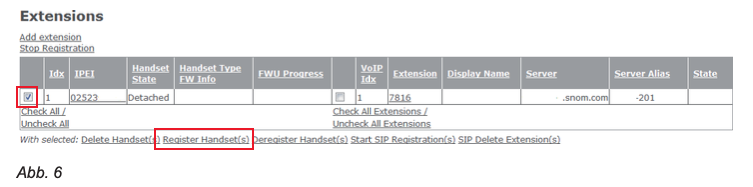
Registering the handset on the M700 - method 2 #
For this method you need to have all handsets within reach. Set up all required extensions as described in the section above “Setting up extensions - M700” on page 22 described. Then proceed as described below for each handset:
- In the table on the user- Click the box to the left of the page Idx and then on Register handset (s).
Open the menu in the handset connection (Fig. 10).
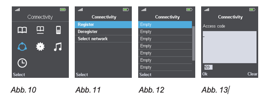
- Choose to register off (Fig. 11).
- M65 / M85: Select a field that the word Empty contains (Fig. 12).
Note: Fields that do not have the word Empty contain, ie contain no or a different designation, have already been registered. If you select one of these fields, you will be asked if you want to overwrite the existing registration.
The M25 supports only one registration and does not display this screen.
- Enter the access code (AC - access code) a.
- In the table on the user- Click the box to the left of the page VoIP Idx and then on Start SIP registration (s).
After the settings have been saved, you will see that the IPEI of the handset has been entered in the table. This means that the handset is registered to use the extension.
- Repeat steps 1 - 6 for all extensions.
M700 emergency alarm settings #
If emergency alarm settings are available, you can select one of the configured profiles for each handset registered on the base station. Emergency alarm settings: “Emergency Alert” on page 37.
Note: Most of the setting options are only available on the M85. With the M65 (default setting) it is possible to call the emergency alarm number set on the base station by pressing and holding the OK / Confirm button on the idle screen. There is no emergency alarm on the M25.
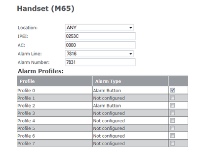
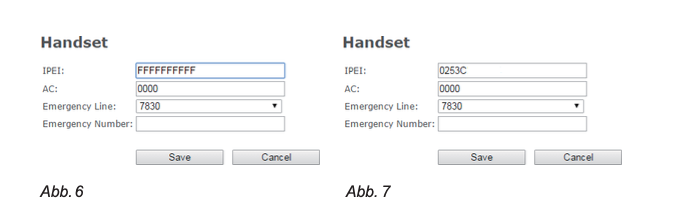
- Open the userPage and click the IPEI of the handset (Fig. 15).
- Select from the pull-down menu Alarm line the extension of the handset (Fig. 16).
- In the From text box, type Alarm Number the phone number to be called in an emergency.
- Choose one of the configured Alarm profiles by checking the box at the end of the line.
- click on to save.
Deregister (de-register) / delete the handset and / or SIP registration on the M700
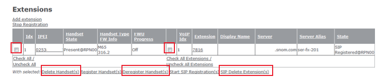
- To de-register a handset, click the box to the left of the Idx and on the link
De-register handset (s).
- To delete the handset from the table, click on the box to the left of the Idx and on the link Delete user.
- To delete a SIP registration, ie an extension, click the box to the left of the VoIP Idxand on the link Delete SIP user.
Extensions - M300 #
In order to be able to use a handset, an extension must be set up on the base station and the handset must be registered for this extension on the base station; in addition there
there two methods. The extensions (or accounts) that are in the German language version user correspond to the "identities" that you know from the corded Snom telephones.
Note: An extension / identity can only be registered by one handset in your DECT system. However, you then have the option of selecting multiple handsets for the extension.
click on userto the page Users and handsets to open. After opening is the page uservisible (Fig. 1), recognizable by the larger font of the word. Click on the link Handsetto display this page instead (Fig. 2).
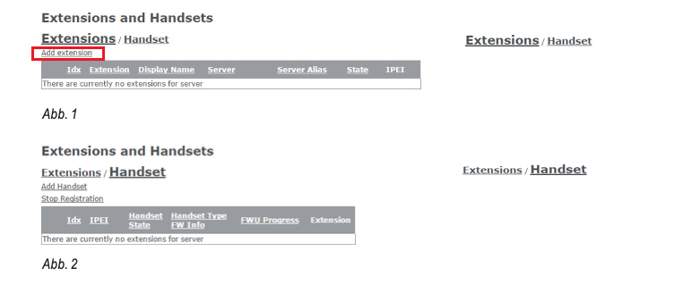
Set up extension and handset - M300 #
- Click on the side user on add user (= Add extension) (Fig. 1). The pageadd user opens (Fig. 3).
The information required may vary depending on the requirements of your telephone system. In any case, it is necessary to enter the extension number (SIP user) and the selection of theservers on which this extension is set up. The other settings depend on the requirements of your telephone system or your IP provider and can remain empty if not required. Please ask your IT administrator or IP provider. Required settings:
- Enter the extension number in the From text field SIP user a.
- If there is more than one SIP server in your network, select the one you want from the pull-down menu of server off if necessary.
- In the table Select handset (s) click on the box on the left of the row Add a handset.
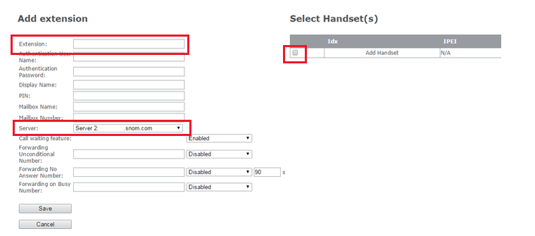
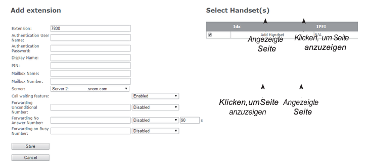
- click on To save.
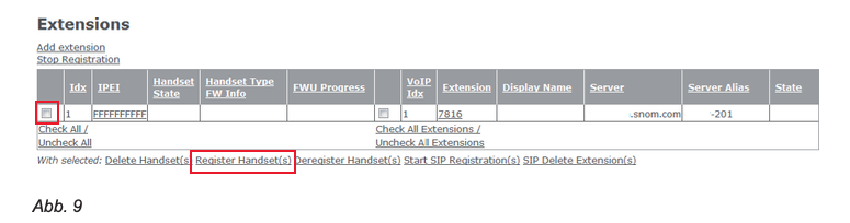
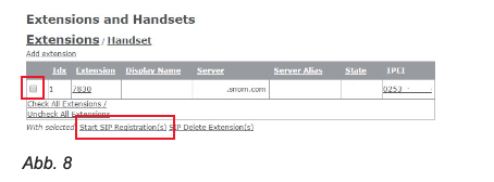
- On the website user click the row of capital Fs in the column IPEI (Fig. 5).
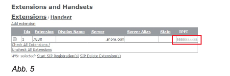
Enter the IPEI of the handset (Fig. 7).
Note: To find the IPEI (International Portable Equipment Identifier), open the menuSettings of the handset, select status and scroll to the Telephone status down, at the end of which you will find the IPEI. The IPEI consists of a series of 10 characters that can be digits or uppercase letters. You omit the colons that divide the characters into groups of two.
- click on to save.
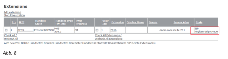
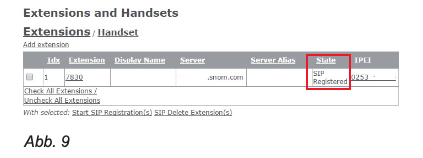
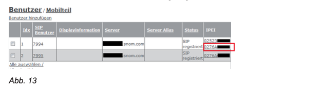
- In the table on the side user you will now see the IPEI in the column IPEI was entered (Fig. 8). Click the box to the left of the idx and click Start SIP registration (s).
If the registration was successful, you will see in the column status the entry SIP registered
(Fig. 9).
Note: In order to be able to use the handset, you must also select the handset from its menu connection above to register log on to the base. For further information, please refer to the operating instructions for the handset.
Select multiple handsets for extension #
- Open the page user and click on the extension.
The page Edit user of the selected extension opens. The selected check boxes in the table Select handset (s) indicate which handset or handsets are using the extension.
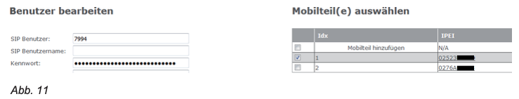
Click the check boxes of the additional handsets that you want the extension to use, e.g. answer incoming calls, etc.
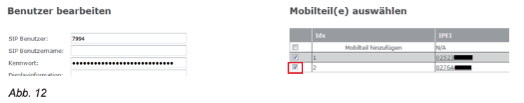
click on to save. The handset or handsets were added to the IPEI field of the extension on the page user added.
M300 emergency alarm settings #
If emergency alarm settings are available, you can select one of the configured profiles for each handset registered on the base station. Emergency alarm settings: "M300 Emergency Alert Settings ”on page 31.
Note: Most of the setting options are only available on the M85. With the M65 (default setting) it is possible to call the emergency alarm number set on the base station by pressing and holding the OK / Confirm button on the idle screen. There is no emergency alarm on the M25.
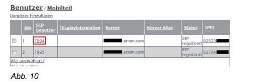
- 1. Open the page Extensions and handsets and click on Handset (see fig. 2 on page 28) and then to the IPEI of the handset. Select from the pull-down menu Alarm line the extension of the handset
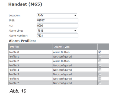
- In the From text box, type Alarm Number the phone number to be called in an emergency.
- Choose one of the configured Alarm Profiles by ticking the box at the end of the line (Fig. 10).
- click on to save.
M300 - delete handset M300 #
- Open the page Handset.
- Click the box to the left of the Idx and up De-register handset (s).
M300 - delete extension #
- Open the page user.
- Click the box to the left of the Idx and up Delete user.
Register M5 repeater #
Up to three M5 repeaters can be connected to a base station. In a system with a single base station, this is always the DECT synchronization source with the RPN00 (Radio Fixed Part Number); the repeaters are given the numbers RPN01, RPN02 and RPN03. In the multi-cell system, you can see the RPNs of the base stations and repeaters on the side Multi-cell check the web interface of the base stations.
There are two DECT sync modes, Manually and Automatically local. The automatic sync mode is recommended for repeaters that are registered directly at the base station or - in the multi-cell system - directly at the primary or a base station of the second level. If repeaters are cascaded, i.e. connected to other repeaters, the manual sync mode must be used.
Note: If you have changed the access code (AC) for registering handsets on the base station, you must change it back to the default setting 0000 in order to be able to register repeaters.
Automatic registration #
When this method is used, the repeater will seek the strongest signal from a base station and the base station will automatically assign it an RPN. This method is recommended for registering repeaters directly to the base station.
- Open the page Repeater.
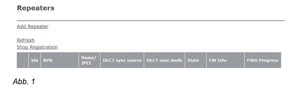
- click on Add repeater (Fig. 1).
- Enter a name for the repeater, e.g. B. a consecutive number or its location (Fig.2). This name appears in the column Name / IPEI on the Repeater-Page (Fig. 3); if you do not enter a name, the IPEI will appear there.
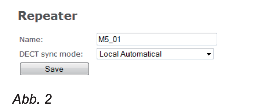
- Select from the pull-down menu of DECT sync mode the setting Automatically local out.
- click on to save.

- Connect the repeater to the mains.
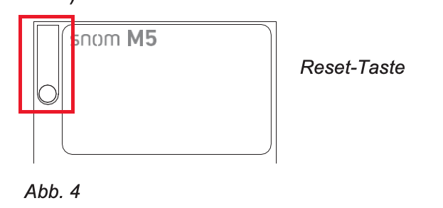
- Press the reset button on the back of the repeater for approx. Two seconds until its LED lights up briefly in red and then flashes green (the green LED flashes twice briefly each time).
Now click on the Repeater-Page on the box to the left of the idx and then on Register repeater.

If the registration was successful, you will see the Repeater-Page the RPNs of the repeater and DECT synchronization source, the IPEI of the repeater and the status "Enabled".

Manual registration #
This method must be used when repeaters are cascaded, ie connected to other repeaters. The RPN of the repeater and that of the DECT synchronization source must be selected manually from the respective pull-down menu.
- Open the RepeaterSide (Fig. 6, above).
- click on Add repeater.
- Enter a name for the repeater, e.g. B. a consecutive number or its location. This name appears in the column Name / IPEI on the Repeater-Page); if you do not enter a name, the IPEI will appear there.
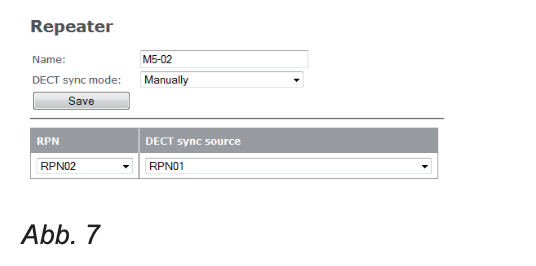
- Select from the pull-down menu of DECT sync mode the setting Manually off (Fig. 7).
Select from the pull-down menu of DECT Sync Source an RPN. In the following example (Fig. 8) the DECT sync source of the second repeater should be the first repeater from Fig. 6, above; therefore RPN01 is selected.
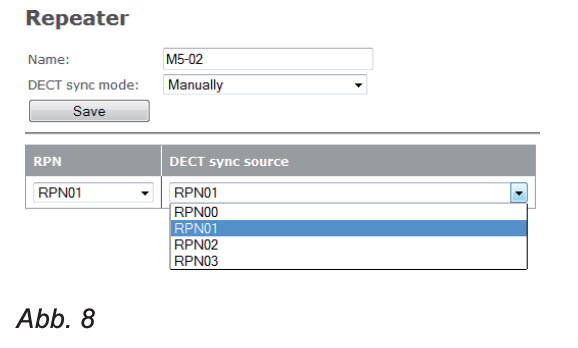
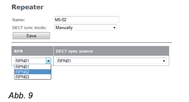
Select from the pull-down menu of RPN select the RPN that the second repeater should receive.
- click on to save.
- Connect the repeater to the mains.
- Press the reset button (see Fig. 4 above) on the back of the repeater for about two seconds until its LED briefly lights up red and then flashes green (the green LED flashes twice each time).
- Now click on the Repeater-Page on the box to the left of the idx and then on Register repeater.

If the registration was successful, you will see the Repeater-Page the RPNs of the repeater and DECT synchronization source, the IPEI of the repeater and the status "Enabled".

Emergency alarm #
From firmware v3.24 B0007. Seven profiles can be configured for the emergency alarm. After configuration, each profile for each handset registered on the base station that is equipped with the emergency alarm function can be used on the userSide of the base station can be selected individually.
Note: All emergency alarm settings are only available on the M85. With the M65 you can use the factory default settings to trigger an emergency call to the adjustable telephone number. There is no emergency alarm on the M25.

- Alarm type. Select from the pull-down menu Emergency button to activate the emergency alarm. Default setting: Deactivated.
- Alarm signal. Call is preset and must not be changed. If the alarm button on the handset is pressed, the handset dials the telephone number set in its alarm configuration (see “M300 Emergency Alarm Settings” on page 31 or. "M300 emergency Alarm settings ”on page 31).
The settings below can only be changed on the M85. Changes do not affect the M65; it always uses the default presets.
- End the alarm from the handset. This setting determines whether or not an alarm can be canceled on the handset. Default setting: Activated.
- Release time (sec.). Enter the number of seconds the handset waits after pressing the emergency key before dialing the emergency number or, if the pre-warning is activated, before the pre-warning time is triggered. Default setting: 0.
- End the pre-warning from the handset. This setting determines whether the pre-warning on the handset can be canceled or not. Default setting: Activated.
- Warning time (sec.). Enter the number of seconds the handset will wait after pressing the emergency button before dialing the emergency number. You will see the message "Pre-warning activated" on the display and the emergency ringtone - if set - will be played. Default setting: 0.
- Beep (only M85). This setting determines whether the handset emits an advisory tone while it is dialing the emergency number. Default setting: Deactivated.
Global phone book #
All handsets registered on the same base station or in the same multi-cell installation can access the global phonebook. The global phone book can consist of a phone list downloaded to the base station / multicell installation or an external source such as a company's LDAP register. It is not possible to edit the list that has been downloaded or made available from an external source on the web interface of the base station or on a handset.
Local phone book #
The local Telephone book is a telephone list that is downloaded to the base station or the primary base station of a multi-cell system.
Note: It is not possible to edit the list on the web interface of the base station or on a handset.
If you want to edit or delete existing entries and add new entries, you must do this in the original file and download the changed file to the base station. The one saved on the base station is completely overwritten.
Create the phone list #
The local phone list must use one of the two formats described below. If there is only one phone number for each name on the list, you can use list type 1. If you want some entries to have more than one number, you must use list type 2.
List type 1
This list is a text file with comma-separated values. Each entry consists of a name and a telephone number. Save the file on your PC or on a server as a text file (* .txt).
Valid values:
- Name: Up to 23 characters are allowed.
- The comma (,) is not allowed because it is used to separate the name and the number. Entries with more than one comma are not saved; there is no indication of the deletion.
- If a name contains more than 23 characters, the excess will be cut off.
- Number: Up to 21 digits are allowed.
- Valid characters: The digits 0 to 9 and the symbol +. You can use parentheses () for the area code and / or spaces to divide numbers into sections, but they will not appear on the handset.
- Numbers with more than 21 characters are deleted without notice.
Examples of valid entries:
Mark, 9345 Jack, +493011111111
Kurt Maier (Snom), 8745 Mary Miller, 9856
Miller Mary, 9856
Dr. Smith, (917) 5550145 Dr. Smith, 917 555 0145 Tim Meier, (040) 111111111
Examples of invalid entries that are deleted without notice:
Dr. Smith, 917-5550145 (Hyphen in number is not allowed) Jack, 030-11111111 (Hyphen in number is not allowed)
Miller, Mary, 9856 (Commas between first and last names are not allowed)
List type 2
This list uses the formats of XML elements. Each entry consists of a name and up to three phone numbers. If there are fewer than three numbers for a name, do not delete the unnecessary elements, but leave the value field blank. Save the file on your PC or on a server either as the type "all files" (*. *) Or as a text file (* .txt).
You can enter up to three phone numbers per name. If there is more than one number for an entry, it is dialed on the handset by pressing the right navigation key.
- Telephone. This entry is indicated by the handset with the symbol
(at home) displayed. If no “office” or “mobile” numbers are configured, the handset displays this number as soon as a name has been selected.
Office. This entry is indicated by the handset with the symbol
(Work) displayed. If configured, the handset displays this number as soon as a name has been selected.
- Mobile. This entry is displayed by the handset with the symbol (mobile phone). If configured and if no office number has been configured, the handset displays this number as soon as a name has been selected.
Note: Enter the number with all required area codes (country / area code, switchboard, operator, etc.). Only the digits 0 to 9 are allowed.
Do not use spaces, brackets, or other characters.
Mandatory elements:
The indentations in the following example, a telephone list with five names, are only intended to provide a better overview.
| IPPhoneDirectory> Name1 Telephone number1 Work / Number 1-> Cell phone number 1 Name2 Work / number2 Name3 Telephone number3 Work / number 3 Name4 Telephone number4 Cell phone number 4 Name5 Telephone number5 > | Number displayed on the handset after selecting the name Number "Office" (work) " Number "Office" (work) " Number "Office" (work) " No "Office" number configured, the mobile phone number is displayed No “Office” or mobile phone number configured, the “Telephone” number is displayed |
Download phone list #
- After you have created and saved the telephone list - as described in the section "Creating the telephone list" - click on Browse (Fig. 29) and select the file saved on the PC or server (Fig. 30). The name of the file is shown to the right of the BrowseButton is displayed (Fig. 31).

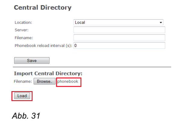
- click on load (Fig. 31).
- Restart the base station.
After downloading the file, its name will no longer appear on the page Global phone book displayed. You can see the content of the imported file on the registered handsets, but not on the base station.
L.DAP #
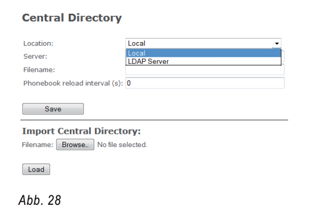
Select on the side Global phone book in the pull-down menu of Location the entry LDAP
off (see Fig. 1 on page 38) to open the LDAP settings menu (Fig. 32). Make the settings required for your LDAP server (e.g. Fig. 33). A restart may be required after saving for the change to take effect.

Settings:
- Server: IP address of the LDAP server.
- Port: The server port for LDAP.
- Sbase: This setting defines the LDAP search base (the "Distinguished Name", ie the LDAP object name or LDAP path) which corresponds to the location of the object in the directory where the LDAP search is to begin. The criteria depend on the configuration of the LDAP server.
- LDAP Filter: The LDAP name filter is the search criterion for the name search. The format corresponds to the string formats of RFC 2254. The default is "empty". (&(telephoneNumber=*)(sn=%))
- Bind: Specifies the username for the LDAP server when the handset connects to the server. If the server allows anonymous bindings, you can leave the text box blank.
- Password: Defines the password for the LDAP server when the handset connects to the server. If the server allows anonymous bindings, you can leave the text box blank.
- Identity settings for the handsets.
- Name: Select the LDAP name attribute from the pull-down menu. You can choose between “cn” (common name) and “sn + givenName” (surname, first name). The default setting is "cn".
- Attributes of the LDAP numbers: The attributes "telephoneNumber" (telephone number), "mobile" (cell phone) and "homephone" (at home) are preset.
Firmware update #
Before starting up the base station (s), you should update to the latest release version of the firmware. Please look up www.snom.com see if there is a new version.
You can either use Snom's update server or download the files to your own server and update from there.
Note: We recommend operating the base station (s) and the connected handsets with the same firmware version.
Although it is possible to update the firmware of a system while it is in operation, we cannot guarantee that there will be no business interruption. We therefore recommend that you update when the entire system is idle or when only a few calls are in progress.
Notes to be observed #
- On average, it takes 10 to 15 minutes to transfer the firmware file to the handsets, but it can take up to 60 minutes depending on the busy status of the base (calls have priority).
- When a handset is in use, the transmission is temporarily suspended. It is continued as soon as the handset is in idle status again.
- After the firmware has been completely transferred, the update of each handset takes about one minute.
- The M700 can update up to 10 and the M300 up to 5 wireless devices at the same time. If a larger number of devices are registered on the base, they are updated one after the other. Note: The base station selects the order of the devices at random. It is not possible to set priorities for individual devices.
- The repeater updates begin automatically as soon as there are no current calls and last about one minute. The repeater cannot be reached during the update.
- Multi-cell installations.
- The M700 updates all handsets within range, including those that are registered at other base stations.
- If a mobile part is moved from the radio range of one base station to that of another, the update will continue as long as sufficient capacity is available.
- When a multi-cell installation is busy with firmware transfers, handover / roaming may fail and calls may be dropped.
- When a firmware update is initiated on a base station, all base stations will perform updates.
Manual update #
Manual updates are carried out in several steps. First, the files for the registered cordless devices are downloaded to the base station. They are then transmitted from the base station to the devices. The base station is then updated.
The handsets are updated as soon as they are placed in the charging station.
Via the Snom Update Server #
On http: //wiki.snom.com/FAQ/snom_M/update_using_dect_snom_com you will find a description of how to use Snom's Update Server as well as the current firmware files for download.
Via its own server #
Before you start the update, you must download all the files you need and save them in folders according to the scheme below.
Do not give the update folders any other names; the base station searches for folders that match the M-series naming scheme. All M-Series product names begin with a capital M followed by one to three digits. Accordingly, the names of the
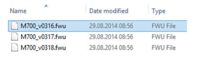
Firmware files also have a capital M followed by one to three digits, e.g., M700, M65, M5. The product name is followed by an underscore _ and on these again a small v and the three-digit firmware version with a leading zero, e.g., 0324, 0355 etc.
Examples:
- The update files for updating the M700 to version 355 must be
M700_v0355.fwu be called.
- The update files for updating the M65 to version 355 must be
M65_v0355.fwu be called.
Download the update files to your own server #
- Set up a folder on your HTTP server for each M-Series product.
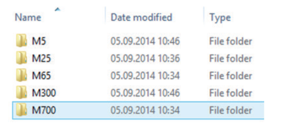
Note: Please note that the letter M is capitalized if you are using an HTTP server with a Linux / Unix operating system. The names of all products in the M series begin with a capital M. The names of the folders must also begin with a capital M, e.g.B. M700, M65, M5. Folders whose names start with a small "m", e.g. B. m700, m65, m5 are not recognized and updates are not performed.
Load the firmware file of each product that you want to update into the respective folder. The folders can contain multiple firmware versions; it is therefore not necessary to delete older firmware versions from the folder before saving.
Download to the base station and transmit to wireless devices
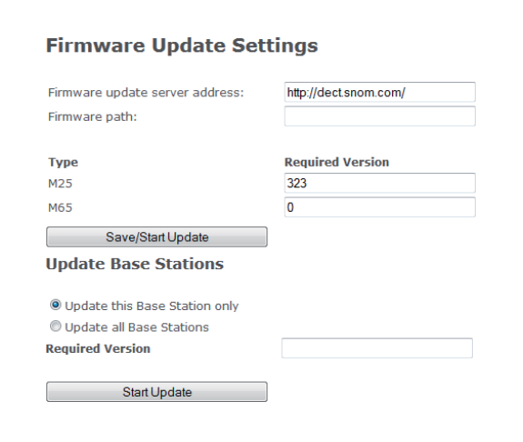
- Open the web interface of the base station and click in the menu on the left Firmware update.
- In the section Firmware update settings in the text box from Address of Firmware update servers its address.
- According to the requirements of your system, enter in the text field of Firmware directory
either enter the firmware path or leave the field blank.
- In the section Type all cordless device types that are registered at the base station are listed, e.g. M65, M25, M5. If no device of a type is currently registered (i.e. ready for operation or in operation), the corresponding device type does not appear. Enter the three-digit version of the firmware, e.g. 355, in the text field of the respective wireless product.
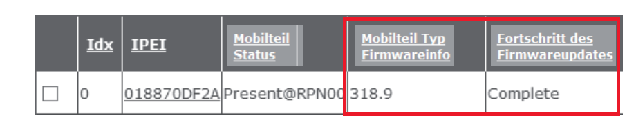
- click on Start save / update. The base station downloads the firmware and transfers it to the cordless devices. On the website user you can follow the progress of the update.
- Handsets only update the next time they are placed in the charging station.
Note: It takes an average of 10-15 minutes to transfer the firmware to the handset, but it can take up to 60 minutes if the network is very busy (calls have priority).
The transmission is interrupted when the handset is in use and continues as soon as the handset switches back to idle mode.

Repeaters carry out the update as soon as there are currently no active calls in the system.
Update the base station #
- In the section Update base stations click on one of the radio buttons. The default is Update this base station only.
- Enter the three-digit firmware version, e.g. 355, to which the firmware is to be updated into the text field of Required version a.
- click on Start save / update.
Update registered handsets #
As described in steps 4 and 5 above, you have transferred the firmware to the handsets registered on the base station. In order to start the update, it is necessary to place each handset in the charging cradle; the update takes about a minute.
- Place the handset in the charging cradle. The LED starts to flash rapidly, first green, then red.
After the update has been completed, the handset switches on again; On the user page you will see the new firmware version and the information that the update has been completed.
Provision updates #
Provisioning is done in Provisioning Guide M700, M300 described. You can find it here: http://wiki.snom.com/Snom_M700/Documentation.
Settings web interface #
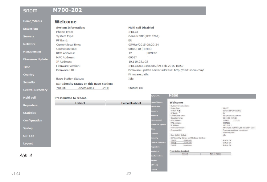
Home / Status #
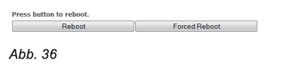
The page Home / Status contains the list of the current status and the current settings of the base station and the handsets and repeaters registered there as well as the buttons for Restart and Forced restart.
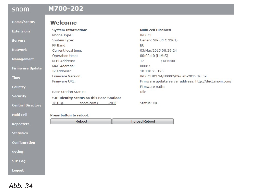
Description of the settings on this page:
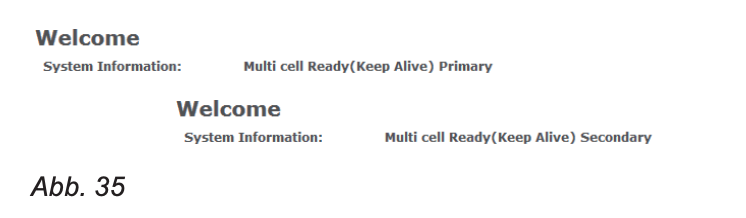
- System information: multicell status of the base station (deactivated, primary base station in a multicell installation, secondary base station in a multicell installation)
- Telephone type: IP DECT
- System type: Custom configuration, if applicable. Default setting: Standard SIP configuration (RFC 3261)
- Frequency band: Depending on the installation location (EU, US, LATAM)
- Current local time: Date and time according to the set local time
- Uptime: Counter - the amount of time since the base station was last restarted
- RFPI number: The Radio Fixed Part Identity (RFPI) is a unique identifier that the base station sends at regular intervals.
- MAC address: The "Media Access Control" address (MAC address) is a unique identifier assigned by the manufacturer.
- IP address: The IP address that the base station received on the network.
- Firmware version: Consists of version number, e.g. 03.55, and branch, e.g. B0021.
- Firmware URL: The address of the server from which the firmware can be downloaded.
- Base station status: "Active" or "At rest"
- SIP identity status on this base station. Shows which handsets registered on the base are currently switched on.
Note: Deactivated handsets are not displayed here. You're still on the sideuser to see; which message is shown in this case depends on your telephone system.
- button Restart: Clicking this button initiates a restart as soon as the base station is in the idle state, i.e. as soon as there are no active calls or other activities of the handsets or firmware updates.
- button Forced restart: Clicking this button initiates an immediate restart; active calls, firmware updates or phone book searches on the handset are canceled.
B.users
M700 #
The table shows the status of the configured extensions and handsets. By clicking the check boxes and buttons, the selected extensions and handsets are registered and de-registered or canceled. registered and deregistered. The configuration is on the sub-pages Add users, edit users and Handset performed. Setting up extensions and registering handsets for extensions: See “User” on page 48 ff.
Note:
- An extension / identity can only be assigned to one handset, regardless of whether you operate a base station as a single device or in a multi-cell installation.
- Each handset only supports one extension / identity per SIP serverregardless of whether the servers are in your network or external to an IP provider.

Settings user side #
| attitude | description |
| Idx | Handset index. The handsets are numbered consecutively by the base station. With checkboxes to mark the registration to and the deregistration and deletion from the base station. |
| IPEI | The "International Portable Equipment Identifier" (IPEI) for DECT handsets is a worldwide unique device number. It consists of the manufacturer's identification, the “Equipment Manufacturer's Code” (EMC), and a serial number assigned by the manufacturer, the “Portable Serial Number” (PSN). |
| Handset status | Present, disconnected, localized, deactivated, activated. Available @ RPNxx: The handset is registered with the base station with number RPNxx (Radio Fixed Part Number). Connection disconnected: The handset is switched off. Localized: The handset is configured for a certain base station, but could not register there, e.g. because the Base station is switched off Deactivated: The handset has not been used for a certain period of time. Activated: Registration for the handset has been set up, but the handset has not yet registered. . |
| Handset type firmware info | Handset model (e.g. M65) and its firmware version (e.g. 355.21) |
| Firmware update progress | While the firmware is being updated, its progress is displayed in this field. Off: No update in progress Initialization: Update initiated x%: Progress of the update in percent Verification x%: Writing of the update finished, progress of the verification in percent Waiting for charging cradle: The firmware has been transferred to the handset; the update begins as soon as the handset is placed in the charging cradle. Connect. term. wait: The firmware was transferred to the repeater; The update starts as soon as there are no current calls Completed: The firmware of the handset / repeater has been updated Error: Update not possible (file not found, file invalid, etc.) |
| VoIP Idx | Index of configured extensions. They are numbered consecutively by the base station. With check box to mark the extension for SIP registration and deregistration. |
| SIP user | The extension number that is also shown on the handset display. |
| Display information | Optional, e.g. name of the user. If entered, the name of the user or similar is shown on the display. |
| server | The server that is on the side add user or. Edit userselected. |
| Server alias | The server alias, if there is an alias on the page server was entered. |
| status | In this field you can see whether the handset and extension are "SIP registered". If the field is blank, it is not. |
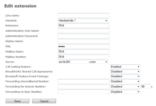
Settings page "Add user" / "Edit user" #
These two pages contain the same settings and are used to set up new or edit existing extensions. The settings Handset, SIP user and server are
always required. The other settings depend on the requirements of the telephone system or the IP provider and can remain empty if not required or desired.
- To the side add user to open it, click add user (Fig. 2).
- To the side Edit user To open it, click the number in the column SIP user (Fig.2).


Description of the settings on the pages add user or. Edit user:
| attitude | description |
| Line name | If necessary / desired. Specifies the name of the line for this extension on the handset. Used when a line needs to be selected for outgoing calls. |
| Handset | Select “New Handset” or one of the consecutively numbered handsets (Handset IDX: 1, 2 etc.) from the pull-down menu. |
| SIP user | The extension or the SIP user name that was configured in the telephone system or on the SIP server. |
| SIP username | If necessary |
| password | If necessary |
| Display information | If necessary or desired |
| attitude | description |
| pin code | This is the PIN for access to the mailbox / answering machine, if available on the telephone system or at the IP provider and / or if necessary.Danger: This is neither the Access Code (AC) for registering the handset at the base station nor the PIN for resetting the handset or for deregistering from the base station. |
| MWI number | If mailbox / answering machine is available in the telephone system or at the IP provider. Name of the user or mailbox number if no text is entered in the text field. |
| Remote inquiry number | Extension number of the mailbox, if the mailbox / answering machine is available in the telephone system or at the IP provider. Often the same number as in the field SIP user.Retrieve messages: Press key "1" for about 3 seconds. |
| server | Select one of the servers from the pull-down menu. |
| Call waiting function | Activate and deactivate the call waiting function. Default setting: Activated (on). |
| BroadWorks Shared Call Appearance | On off. Default setting: Deactivated (off). Split line - only for Broadsoft applications. |
| BroadWorks Feature Event Package | On off. Default setting: Deactivated (off). For Broadsoft applications only. If activated, the extension registers for the Broadsoft Application Server Feature Event Package and is ready to receive SIP Notify with the status for the Broadsoft server services "please do not disturb (DND)" and "call forwarding" (always (always ), if busy, after a timeout (delayed forwarding (no answer)). |
| Immediate redirection | On off. All incoming calls to this extension are immediately forwarded to the telephone number entered in the text field. Note: This setting (both the number and the activation / deactivation) can be changed on the handset registered for the extension. Preset: Empty text field, status off (deactivated) |
| Delayed diversion | On off. All incoming calls to this extension are forwarded to the telephone number entered in the text field after the number of seconds entered in the seconds field. Note: This setting (number, number of seconds, activation / deactivation) can be changed on the handset registered for the extension.Preset: Empty text field, status off (deactivated) |
| Forwarding when busy | On off. If the extension is busy, all incoming calls are diverted to the phone number entered in the text field. Note: This setting (both the number and the activation / deactivation) can be changed on the handset registered for the extension.Preset: Empty text field, status off (deactivated) |
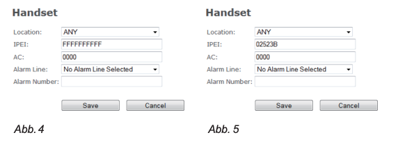
Handset settings #
Click on the IPEI or the FFFF placeholder to open the page. If you click on the IPEI of a registered handset, the handset model (M65, M85 or M25) is added to the page heading (Fig. 5).


Description of the settings on the page Handset:
| attitude | description |
| Location / place | In a multi-cell installation, you can select a specific base station from the pull-down menu, if several are available. Default setting: Any |
| IPEI | You can find the IPEI in the menu Settings of the handset, setting Status. Scroll to the IPEI at the end of the Phone status down. The IPEI consists of a series of 10 decimal numbers and capital letters. If you want to enter the IPEI manually, leave out the colons between the characters. |
| Access code | This is the number (Access Code - AC) for registering the handset with the base station. The default setting is 0000 (4 x zero). Danger: This is neither the PIN for accessing the mailbox / answering machine nor the PIN for resetting the handset or for deregistering from the base station (default setting also 0000). |
| Alarm line | M85 / M65 only. This is the extension number for which the handset is registered. Default setting: Off (No Alarm Line Selected). |
| Alarm Number | M85 / M65 only. This is the number the handset will call when the distress alert is raised. |
| Alarm Profiles (Configurations for emergency button on M65 and M85; not available on M25)) | |
| Profiles | If on the emergencyPage an alarm profile has been configured and a profile name has been entered, it is displayed in brackets after the consecutive number of the profile (e.g. Profile 0 (Shop)). To select it, click on the checkbox of a configured Emergency button. |
| Alarm type | If on the emergency-Page an alarm profile has been configured is shown hereEmergency button. |
| attitude | description |
| Import local phone book | |
| These are the individual contacts that are only saved on your handset and are located in the Contacts menu | |
| Export local phone book | |
| These are the individual contacts that are only saved on your handset and are located in the Contacts menu |
M300 #
Settings on the Users and Handsets page #
The font size indicates whether the settings of user (ie, extension) or from
Handset are displayed.
The settings of the extensions are displayed:
| attitude | description |
| Idx | Handset index. The handsets are numbered consecutively by the base station. With checkboxes to mark the registration to and the deregistration and deletion from the base station. |
| SIP user | The extension or the SIP user name that was configured in the telephone system or on the SIP server. |
| Display information | Optional, e.g. name of the user. If entered, the name of the user or similar is shown on the display. |
| server | The server that is on the side add user or. Edit userselected. |
| Server alias | The server alias, if there is an alias on the page server was entered. |
| status | In this field you can see whether the handset and extension are "SIP registered". If the field is blank, it is not. |
| IPEI | The "International Portable Equipment Identifier" (IPEI) for DECT handsets is a worldwide unique device number. It consists of the manufacturer's identification, the “Equipment Manufacturer's Code” (EMC), and a serial number assigned by the manufacturer, the “Portable Serial Number” (PSN). |
Add / edit users #
These two pages contain the same settings and are used to set up new or edit existing extensions. The settings Handset, SIP user and server are
always required. The other settings depend on the requirements of the telephone system or the IP provider and can remain empty if not required or desired.
- To the side add user to open it, click add user.
- To the side Edit user To open it, click the number in the column SIP user.
Description of the settings on the pages add user or. Edit user:
| attitude | description |
| SIP user | The extension or the SIP user name that was configured in the telephone system or on the SIP server. |
| SIP username | If necessary |
| password | If necessary |
| Display information | Optional, e.g. name of the user. If entered, the name of the user or similar is shown on the display. |
| pin code | This is the PIN for access to the mailbox / answering machine, if available on the telephone system or at the IP provider and / or if necessary.Danger: This is neither the Access Code (AC) for registering the handset at the base station nor the PIN for resetting the handset or for deregistering from the base station. |
| MWI number | If mailbox / answering machine is available in the telephone system or at the IP provider. Name of the user or mailbox number, if the text field is empty. |
| Remote inquiry number | Extension number of the mailbox, if the mailbox / answering machine is available in the telephone system or at the IP provider. Often the same number as in the field SIP user.Retrieve messages: Press key "1" for about 3 seconds. |
| server | Select a server from the pull-down menu. |
| Call waiting function | Activate and deactivate the call waiting function. Default setting: Activated (on). |
| Immediate redirection | On off. All incoming calls to this extension are immediately forwarded to the telephone number entered in the text field. Note: This setting (both the number and the activation / deactivation) can be changed on the handset registered for the extension.Preset: Empty text field, status off (deactivated) |
| Delayed diversion | On off. All incoming calls to this extension are forwarded to the telephone number entered in the text field after the number of seconds entered in the seconds field. Note: This setting (number, number of seconds, activation / deactivation) can be changed on the handset registered for the extension.Preset: Empty text field (function switched off / deactivated) |
| Forwarding when busy | On off. If the extension is busy, all incoming calls are diverted to the phone number entered in the text field. Note: This setting (both the number and the activation / deactivation) can be changed on the handset registered for the extension.Preset: Empty text field, status off (deactivated) |
| table Select handset (s) | |
| Idx | Click on the check box (s) to select “Add handset” or one or more of the existing handset idx. |
| attitude | description |
| IPEI | The "International Portable Equipment Identifier" (IPEI) for DECT handsets is a worldwide unique device number. It consists of the manufacturer's identification, the “Equipment Manufacturer's Code” (EMC), and a serial number assigned by the manufacturer, the “Portable Serial Number” (PSN). |
The handset settings are displayed:
| attitude | description |
| Idx | Handset index. The handsets are numbered consecutively by the base station. With checkboxes to mark the registration to and the deregistration and deletion from the base station. |
| IPEI | The "International Portable Equipment Identifier" (IPEI) for DECT handsets is a worldwide unique device number. It consists of the manufacturer's identification, the “Equipment Manufacturer's Code” (EMC), and a serial number assigned by the manufacturer, the “Portable Serial Number” (PSN). |
| Handset status | Indication of the current status of the respective handset in the network: Available @ RPNxx: The handset is registered on the base station with number RPNxx (Radio Fixed Part Number) Disconnected: The handset is switched off Localized: The handset is configured for a specific base station, but could not register there, e.g. because the base station is switched off. Deactivated: The handset has not been used for a certain period of time. Activated: The registration for the handset has been set up, but the handset has not yet registered. |
| Handset type firmware info | Handset model (e.g. M65) and its firmware version (e.g. 355.21) |
| Firmware update progress | While the firmware is being updated, its progress is displayed in this field. Off: No update in progress Initialization: Update initiated x%: Progress of the update in percent Verification x%: Writing of the update finished, progress of the verification in percent Waiting for charging cradle: The firmware has been transferred to the handset; the update begins as soon as the handset is placed in the charging cradle. Connect. term. wait: The firmware was transferred to the repeater; The update starts as soon as there are no current calls Completed: The firmware of the handset / repeater has been updated Error: Update not possible (file not found, file invalid, etc.) |
| SIP user | The extension to which the handset is registered. |
Handset settings #
click on Add handsetto the page Handset to open; the text field of "IPEI" contains the placeholder FFFF. If you click on the IPEI of a handset, the page opens Handset with the settings of this handset; the text field of "IPEI" contains the ten-digit character string of the IPEI, consisting of digits and capital letters.
| attitude | description |
| IPEI | The "International Portable Equipment Identifier" (IPEI) for DECT handsets is a worldwide unique device number. It consists of the manufacturer's identification, the “Equipment Manufacturer's Code” (EMC), and a serial number assigned by the manufacturer, the “Portable Serial Number” (PSN). |
| Access code | This is the number (Access Code (AC)) for registering the handset with the base station. The default setting is 0000 (4 x zero). Danger: This is neither the PIN for accessing the mailbox / answering machine nor the PIN for resetting the handset or for deregistering from the base station (default setting also 0000). |
| Alarm line | M85 / M65 only. This is the extension number for which the handset is registered. Default setting: Off (No Alarm Line Selected). |
| Alarm Number | M85 / M65 only. This is the number the handset will call when the distress alert is raised. |
| Alarm Profiles (Emergency button configurations on M65 and M85; not available on M25). More information: see “Emergency Alert” on page 37 and “Emergency” on page 79. | |
| Profiles | If on the emergencyPage an alarm profile has been configured and a profile name has been entered, it is displayed in brackets after the consecutive number of the profile (e.g. Profile 0 (Shop)). To select it, click on the checkbox of a configured Emergency button. |
| Alarm type | If on the emergency-Page an alarm profile has been configured is shown hereEmergency button. |
| Import local phone book | |
| These are the individual contacts that are only saved on your handset and are located in the Contacts menu | |
| Export local phone book | |
| These are the individual contacts that are only saved on your handset and are located in the Contacts menu |
S.erver #
On this page you can add and remove SIP / NAT servers, select the server (registrar) with which the base station is to register and change the default settings.

Description of the settings:
| attitude | description |
| Server alias | Server alias. Preset: Empty. |
| NAT support | Preset: Disabled. All SIP messages go directly to the NAT gateway.NOTE:Activated: If the base station receives a SIP response to a REGISTER request with a “Via” header containing the “received” parameter (for example: Via: SIP / 2.0 / UDP 10.1.1.1:4540;received=68.44.20.1), adapt your contact information to the IP address of "received" and send another REGISTER request with the updated contact information. Deactivated: The base station ignores the parameter "received". |
| Registrar | DNS or IP address of the SIP server proxy. Specifying the port number is optional. |
| Outbound proxy server | DNS or IP address of the session border controller or outgoing proxy address of the SIP server. Set the outbound proxy to the address and port of the private NAT gateway so that SIP messages are sent via this gateway. Format: addr: portPreset: Empty |
| Conference server | For Broadsoft conference servers only: If you enter the IP address of the server in the text field, a connection to the conference server is established by pressing the conference function key on the handset during a call. If the text field is left blank, pressing will set up the system's 3-way conference. |
| attitude | description |
| Reregistration time (s) | The “expires” value in SIP REGISTER requests. This value indicates how long the current SIP registration remains valid, i.e. the set period in seconds between SIP registrations of the SIP account. Valid values: Maximum 65636 seconds. We advise against values of less than 60 seconds.Presetting: 3600 |
| SIP session timers | RFC 4028. The value for the SIP session timer is the maximum time between “keep-alives”, ie session refresh signals. If no signal is received when the time has elapsed, the call is ended.Presetting: Activated. |
| Session timer value (s) | Presetting: 1800 seconds. Valid values: minimum 90 seconds, maximum 65636 seconds. If the setting is deactivated, no session timer is used. |
| SIP transport | Presetting: UDP. Other options: TCP, TLS 1.0 |
| Signal TCP source port | If TCP or TLS was selected in the "SIP Transport" setting, a TCP or TLS connection is set up for each SIP extension. The origin of the connection is determined by the TCP stack; the local SIP port parameter is not used. This setting determines whether the originating port used should be clearly addressed in the SIP messages.Presetting: Activated. |
| Use one TCP connection via SIP extension | If TCP or TLS is set as the SIP Transport, you can select here whether the base station has a TCL or TLS connection for each SIP extension or a TCL or TLS connection for all SIP extensions should set up. Note: If TLS is used and the SIP server requires client authentication, ie a client certificate, this setting must be deactivated.Settings: Deactivated (a TCL or TLS connection for all SIP extensions) Activated (a TCL or TLS connection for each SIP extension)Presetting: Disabled |
| RTP from own base station | If deactivated, the RTP data are transmitted by the base station in whose frequency range the handset is currently located. If activated, the RTP data is always transmitted from the base station on which the handset is registered.Presetting: Activated |
| Automatic connection check (keepalive) | Presetting: Activated. If this setting is activated, keepalive messages are sent to the registrar / proxy port every 30 seconds so that the port remains open and the phone can be reached. |
| Show extension on handset display (in idle state) | Presetting: Activated. When activated, the extension number is shown on the handset display when the handset is idle. |
| Maintain behavior | Determines the behavior of the handset's "Hold" function. The available options are: RFC 3264: Hold is signaled in accordance with RFC 3264, i.e. the part of the Session Description Protocol (SDP) with the connection information contains the IP address of the end device and the direction attribute required, depending on the context. sendonly, recvonly or inactive Data streams. RFC 2543: The "old" way of signaling a call on hold. The part of the Session Description Protocol (SDP) with the connection information is set to 0.0.0.0 and the Direction Attribute is required, depending on the context, sendonly, recvonly or inactive Data streams.Presetting: RFC 3264. |
| attitude | description |
| Attended Transfer Behavior (forwarding with announcement) | Depending on whether the telephone system requires the call to be active (ie not on hold) before REFER is sent, this setting determines whether the second call is put on hold when the handset's "Transfer" button is pressed Hold 2nd Call Setting: Put the call on hold before sending REFER Do Not Hold 2nd Call setting: Send REFER without putting the call on hold.Presetting: Hold 2nd call |
| Use your own codec priority | This setting determines whether the codec priority of the base station (setting activated) or that of the incoming call (setting deactivated) is used.Presetting: Disabled |
| DTMF signaling | This setting determines how the decimal numbers as well as the asterisk and pound keys ('*', '#') are converted into tones with speech characteristics. Data packet sent. RFC 2833: The DTMF tone is "analyzed" and sent as a value in an RTP packet. Both: SIP INFO and RFC 2833Presetting: RFC 2833 |
| DTMF payload type | This setting defines the value for the DTMF data type (RFC2833).Presetting: 101 |
| Evaluation of Caller ID (data field) | SIP information field for Caller ID. Options: PAI - FROMFROMALERT_INFO - PAI - FROM |
| Activate connection without consultation | Forwarding without confirmation. This setting determines whether forwarding without consultation is possible (activated) or not.Presetting: Activated |
| Codec priority | This setting defines the codec priorities for audio compression and transmission. If the priority order with the High/DownButtons have been changed, then click Reset codecs.Note: For a multi-cell installation, you must also click the button on the Multi-cell page Restart chain click to update the handsets.Options: G.722; G.711A-law, �-law; G.726Note:If G.722 is in the list, the codec negotiation algorithm is activated. As a result, the time required to set up the handsets is slightly longer than without G.722. If G.722 is at the top of the order of priority, the number of simultaneous calls per base station is reduced from 10 (8) to 4. |
| RTP packet size | This setting defines the preferred RTP packet size for RTP packet negotiations.Presetting: 20 ms |
| Safe RTP | If this setting is activated, RTP is encrypted with the key negotiated during the call setup via the SDP protocol (AES-128).Presetting: Disabled. |
| attitude | description |
| Secure RTP Auth | When this setting is enabled, secure RTP (SRTP) uses the authentication of the RTP packets.Note: With activated SRTP authentication, a maximum of 4 simultaneous calls per base station are possible, both in individual operation and in a multi-cell installation.Presetting: Disabled. |
| SRTP Crypto Suites | Supported SRTP Crypto Suite: AES_CM_128_HMA_SHA1_32 |
Nnetwork
| attitude | description |
| IP settings | |
| DHCP / Static IP Address | Allows protocol changes to receive dynamic IP addresses. When DHCP is set, the remaining IP settings and options are not available. DHCP: IP addresses are assigned automatically from the pool of available IP addresses. Static IP: IP addresses are assigned manually by the network administrator.Preset: DHCP. |
| IP address | Only available with the "Static IP address" setting. In this case, enter the static IP address here. |
| Subnet mask | Only available with the "Static IP address" setting. In this case, enter the subnet mask here. |
| Standard gateway | Only available with the "Static IP address" setting. In this case, enter the IP address of your router here. |
| DNS (primary) | Only available with the "Static IP address" setting. In this case, enter the address of the Internet provider's DNS server here. |
| DNS (secondary) | |
| VLAN settings | The VLAN settings are used in networks with separate virtual LANs (VLAN) for voice and data traffic. In these networks, the base station can mark voice files that it generates in a “voice VLAN” using the IEEE 802.1q specification with special VLAN markings. |
| ID | 12-bit identifier of the 802.1q VLAN. Allowed values: Positive integers from 0 to 4094. The default setting 0 is used to identify “priority frames”; the setting 4095 (eg FFF) is reserved. If the default setting is 0, neither VLAN tagging nor VLAN search via DHCP is carried out.Preset: 0. |
| User priority | 3-bit value to define the user priority, values from 0 ("best effort" - best / fastest possible transmission) and 1 to 7 (lowest to highest priority). The values can be used to prioritize different classes of data traffic (voice, video, data, etc.).Preset: 0 |
| synchronization | When this setting is enabled, the VLAN ID is automatically synchronized between the base stations in the multicell chain. They are automatically restarted during synchronization.Preset: Disabled. |
| DHCP options | |
| Plug-n-play | If this setting is activated, the DHCP option 66 is used to automatically transfer the IP address from the telephone system to the base station.Preset: Disabled. |
| NAT settings | |
| Use the STUN server | Preset: Disabled. Select “Enabled” to use STUN. |
| STUN server | Allowed values: IPv4 values or URL. |
| Define the STUN binding time | Preset: Disabled. |
| Protect STUN binding time | Time in seconds. Allowed values: Positive integers.Preset: 80. |
| attitude | description |
| Switch on RPORT | Preset: Disabled. Select "Enabled" to use RPORT in SIP messages. |
| Automatic connection check (keep-alive time) | The time intervals in seconds in which the base station transmits a keep-alive signal to the SIP server in order to maintain the NAT connections. Allowed values: Positive integers.Preset: 90. |
| SIP / RTP settings | |
| Select other SIP ports | When disabled, this setting determines the origin used by the system for SIP signaling; when enabled, it determines the origin used by the first user agent (UA). The following UAs get the following ports.Preset: Disabled. |
| RTP collision detection | Activated: If two sources have the same SSRC identification, the second RTP is discarded. Deactivated: SSRC identification is not checked; all sources are accepted.Preset: Enabled. |
| Local SIP port | Port for the SIP signaling.Allowed value and default setting: 5060. |
| SIP ToS / Qos | IP priority of the signaling traffic for connection control based on both IP layers of “Type of Service” (ToS) bytes. In packet-based networks, ToS is called “Quality of Service” (QoS).Allowed values: Positive integers; the default is 0x68. |
| RTP port | The first RTP port for RTP streaming.Allowed value and default setting: 50004 (depending on the system). |
| Scope of the RTP ports | The number of ports that can be used for RTP audio streaming.Allowed values: Positive integers; the default is 40. |
| RTP TOS / QoS | Priority of the RTP traffic based on the ToS byte of the IP layer. In packet-based networks, ToS is called “Quality of Service” (QoS). For details see RFC 1349. The “cost“ bit is not supported. Bit 7..5 defines the order of precedence Bit 4..2 defines the Type of Service (ToS) Bit 1..0 is ignoredAllowed values: Default setting 5060. |
| SIP registration mode | Static or plug and play.Preset: Plug-n-Play |
management #
On this page of the web interface of the base station, settings for HTTP, downloading the configuration, text messaging and system and SIP logs are specified.
| attitude | description |
| Base station name | This name appears in the header of the web interface of the base station and as its name in the base station group and in the DECT chain of a multi-cell system.Presetting: The name of the model, that is, M700 or M300. If you operate more than one base station, it is advisable to give them unique names such as M700-01, M700-02, M700-Rm12 or similar.Maximum number of characters: 35 |
| Settings | |
| HTTP management username | Allowed values: 8-bit string |
| HTTP management password | Password for access to the configuration server. HTTP client authentication consists of the HTTP management usernamen and this password.Allowed values: 8-bit string |
| Enable automatic prefix | Disabled: No automatic prefix number is added.Activated: The base station adds the in the setting Define the prefix for outgoing calls specified number before the dialed number.Enabled, exclude * and #: Enables * or # to be recognized as the first character of a number entered on the handset. In this case the base station does not add a 0 before the dialed number. Examples: 1: Dialed number * 1234 -> number transmitted to the telephone system * 12342: Dialed number #1234 -> number transmitted to the telephone system #12343: Dialed number 1234 -> transmitted to the telephone system Number 01234Preset: Disabled. |
| Define the maximum number of digits for internal numbers | This setting is used to recognize internal numbers. Prefix numbers are not added to internal numbers.Preset: 0. |
| Define prefix for outgoing calls | Prefix number that is added in front of the entered number when the "Activate automatic prefix" setting is activated.Allowed values: 1 to 9999.Preset: Empty. |
| configuration | |
| Configuration server address | DNS or IP address of the server from which the base station gets the configuration file.Allowed values: IP address or URL.Preset: Empty. |
| Filename | Preset: Empty. |
| Text messaging | |
| Text messaging | Disabled enabled: Messaging via server, if provided by an external service provider.Activated without a server: Allows handsets to send messages to other handsets that support this function.Preset: Disabled. |
| attitude | description |
| Text Messaging & Alarm Server | Allowed values: IP address or url.Preset: Empty. |
| Text messaging port | Port number of the message server.Preset: 1300. |
| Text messaging automatic connection check keepalive (m) | Time span in minutes between keep-alive messages.Allowed values: Positive integers.Preset: 30. |
| Text messaging response (s) | Response timeout period in seconds.Allowed values: Positive integers.Preset: 30. |
| Text messaging TTL | Text messaging time-to-live (TTL) in seconds. Allowed values: Positive integers.Preset: 0. |
| Syslog / SIP log | |
| Upload the SIP log file | If this setting is activated, low-level SIP debug messages (messages for troubleshooting) are saved on the server in the following format: |
| SIP log server address | Allowed values: IP address or URLPreset: Empty. |
| Syslog level | Out: Data is not saved on the syslog server.Standard operation: Normal operating events (incoming and outgoing calls, registration of handsets, DECT location, calls rejected due to busy) as well as critical system errors and general system information are saved.System analysis: In addition to the data of standard operation, handset roaming and firmware update statuses of handsets are saved.Debug: Used by Snom for troubleshooting. Should not be set during normal operation.Preset: Standard operation. |
| Syslog server IP address | Allowed values: IP address or url.Preset: 0. |
| Syslog server port | Port number of the syslog server.Preset: 514. |
Firmware update #
| attitude | description |
| Address of the firmware update server | IP address or DNS of the source for the update.Allowed values: IP address or URL. Note: Cannot end with a slash /.Examples: http://dect.snom.com, 10.10.104.41Preset: Empty. |
| Firmware directory | If necessary: Specify the directory on the server or the path to the directory in which the update files are located.Note: Must start with a slash /.example: /M700_v0355.fwuPreset: Empty. |
| Type | All handset and repeater types (ie M65, M85, M25, M5) that have been registered on the base station, even if no device of the respective type is currently switched on. |
| Required version (handsets and repeaters) | Firmware version to which the respective handset and / or repeater type is to be updated. Note: The value 0 deactivates the update for handsets and repeaters.Allowed values: 8-bit stringexample: 355Preset: 0. |
| Required version (base station) | Firmware version to which the base station is to be updated.Allowed values: 8-bit string example:355Preset: Empty. |
| Required "Branch" | E.g. B.21 if necessary. |
| Update this base station only / Update all base stations | M700 only. In a multi-cell system, click on the respective radio button, depending on whether you only want to update the firmware of the base station on whose web interface you are, or the firmware of all base stations in the system. |
Time settings #
The specification of the time server is absolutely necessary in the multi-cell systembecause it is required for data synchronization. It is also used in the debug and SIP logs and to determine when to check for the availability of new configuration and firmware files.
Note: Multi-cell systems do not work without a configured time server.
If the time server setting is changed, the system must be restarted. Click the button Save and restart. Depending on how many base stations are connected in the system, it can take up to 15 minutes for all of them to be synchronized.
The setting of a time server is optional for base stations in individual operation. See also “Language, Country, Time / Date” on page 21.
| attitude | description |
| Time server | IP address or DNS of the NTP server. Allowed values: IP address (IPv4 only) or URL. Preset: Empty. |
| Allow NTP transmission | Click to use the entered time server.Preset: Clicked (activated). |
| Update interval (h) | Time span in hours between time updates.Allowed values: Positive integers.Preset: 1. |
| Use the time zone of the country / region | When the box is checked, the will appear on the page Country settings selected time zone used. If not, the time zone (UTC +/-) can be selected from the pull-down menu on the page Time settings to get voted.Note: Are the boxes of Country's time zone / of the region and Country Summer Time /of the region on the website Country settings Clicked on or off, the settings are on both the Time settings as well as on the side Country settings activated or deactivated.Preset: Clicked (activated). |
| Time zone | Select the time zone (UTC +/-) from the pull-down menu.Preset: Checked (enabled). This setting is not available if the setting is Use the time zone of the country / region is clicked. |
| Use country / region daylight saving time | When the box is checked, the will appear on the page Country settingsselected daylight saving time is used.Note: Are the boxes of Country's time zone / of the region and Country Summer Time /of the region on the website Country settings Clicked on or off, the settings are on both the Time settings as well as on the side Country settings activated or deactivated.Preset: Clicked (activated). |
| attitude | description |
| The following settings are disabled when Use country / region daylight saving time is clicked. If not, daylight saving time can be configured manually on this page | |
| Summertime | Select disabled, enabled, or automatic from the pull-down menu.Activated: Daylight saving time starts / ends immediately, none of the following settings are availableDeactivated: None of the following settings are available and daylight saving time is not applied.Automatically: Summer time begins and ends automatically on the set date at the set time.Preset: Automatically |
| Daylight saving time tied to a day | Use month and date: If you want to enter a date. If this setting is selected, the text fields of “Summer time starts on (date)”, “Summer time starts at (time)”, “Summer time ends on (date)” and “Summer time ends at (time)” are available.Use month and day of the week: If you want to enter a day of the week. If this setting is selected, the text fields are "Day of the week on which daylight saving time begins", "Daylight saving time begins on", "Daylight saving time starts at (time)", "Day of the week on which daylight saving time ends", "Daylight saving time ends on" and "Daylight saving time ends at (time) ”available. |
| Daylight saving time starts in the month | Select the month from the pull-down menu.Preset: March |
| Daylight saving time starts on (date) | If “Daylight Saving Time” is set to “Use month and date”, enter the day in the text field.Allowed values: Positive integers 1-31.Preset: 0 |
| Daylight saving time starts at (time) | Enter the time in the text field. Allowed values: Positive integers 0-23. Preset: 2 |
| Day of the week on which daylight saving time begins | If "Daylight Saving Time" is set to "Use month and day of the week", select the day of the week from the pull-down menu.Preset: Sunday |
| Daylight saving time starts on | If “Daylight Saving Time” is set to “Use month and day of the week”, select the week of the month from the pull-down menu. Options: First, last, second, penultimate, third (e.g. Sunday) of the month Preset: Last of the month (i.e. day of the week in the last week of the month) |
| Daylight saving time ends in the month | Select the month from the pull-down menu.Preset: October |
| Daylight saving time ends on (date) | If “Daylight Saving Time” is set to “Use month and date”, enter the day in the text field.Allowed values: Positive integers 1-31.Preset: 0 |
| Daylight saving time ends at (time) | Enter the time in the text field. Allowed values: Positive integers 0-23. Preset: 2 |
| Day of the week on which daylight saving time ends | If "Daylight Saving Time" is set to "Use month and day of the week", select the day of the week from the pull-down menu.Preset: Sunday |
| Daylight saving time ends on | If "Daylight saving time" is set to "Use month and day of the week", select the week of the month from the pull-down menu. Options: First, last, second, penultimate, third (e.g. Sunday) of the month Preset: Last of the month (i.e. day of the week in the last week of the month) |
Country settings #
| attitude | description |
| choose country | The selection of the country determines which in-band tones the base station uses (dial tone, ring tone, busy, call waiting). Select a country from the pull-down menu. |
| State / Region | This pull-down menu is available if the selected country has more than one time zone, such as the USA or Australia. In this case, select a state or region from the pull-down menu. |
| Select your language | The language for the web interface of the base station can be set independently of the country set. Select a language from the pull-down menu.Preset: The lingua franca of the set country. |
| Use the time zone of the country / region | If the box is checked, the base station will use the time zone of the selected country / region. If the box is not checked, the time zone can be set manually from the pull-down menu on the page Time settings to be selected.Note: If the box of Country's time zone / of the region checked or unchecked, the settings on this page as well as on the pageTime settings activated or deactivated.Preset: Clicked (activated). |
| Use daylight saving time in the country / region | If the box is checked, the base station will use the daylight saving time of the selected country / region.Note: If the box of Use country / region daylight saving time If you clicked on or off, the settings on this page as well as on the pageTime settings activated or deactivated.Preset: Clicked (activated). |
| notes | Only for countries such as the USA and Brazil, in which individual areas have different time settings than the time zone in which they are located. In this case, the exceptions are listed here. |
Network security #
This page is used to download Trusted Certificates and SIP client certificates to the base station and delete them from the base station. You can also select the use of the integrated secure web server (HTTPS) and change the password for opening the web interface.
NOTE: SIP and RTP security depend on the server.
Certificates
| attitude | description |
| Idx | Index number.Preset: Given. |
| Issued to (issued for) | IP address or organization / company. This information is part of the certificate file.Preset: Empty |
| Issued to (issued for) | Organization / company / department. This information is part of the certificate file.Preset: Empty |
| Valid until (Date of Expiry) | Date time year. This information is also part of the certificate file.Preset: Empty |
| Use only trusted certificates (only use trusted certificates) | You can use the pull-down menu to specify that only trustworthy certificates may be used.Preset: Disabled. |
Import trusted certificates
The supported format is the DER-encrypted binary file X.509 (.cer).
- Click the button Browse and select the file on your PC or server. The name of the selected file appears to the right of the browse button.
- click on Load. The certificate is loaded.
SIP client certificates
| attitude | description |
| Idx | Index number.Preset: Given. |
| Issued to (issued for) | IP address or organization / company. This information is part of the certificate file.Preset: Empty |
| Issued to (issued for) | Organization / company / department. This information is part of the certificate file.Preset: Empty |
| Valid until (Date of Expiry) | Date time year. This information is also part of the certificate file.Preset: Empty |
Import SIP Client Certificate and Key Pair
The supported format is the DER-encrypted binary file X.509 (.cer); the keys must be an unencrypted PKCS#8 binary file (.key).
Note: Client certificate and key pair must be downloaded at the same time.
- Click the button Browse and select both files on your PC or server.
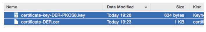
The name of the selected file appears to the right of the browse button.
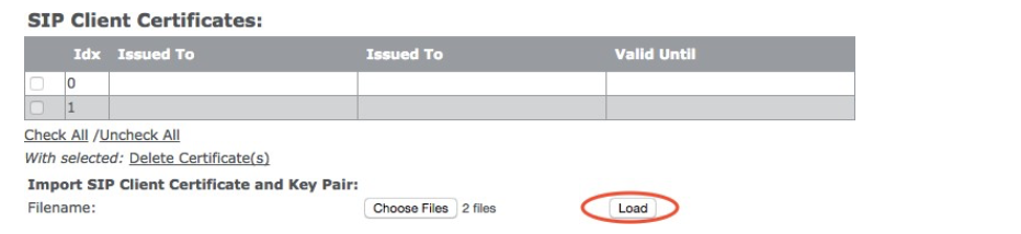
click on Load. The certificate and key pair are loaded.
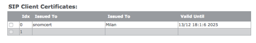
password #
| attitude | description |
| User name | Any allowed character, up to 15.Preset: admin |
| Current password | Any allowed character.Preset: admin |
| New password | Any allowed character, up to 15.Preset: Empty |
| confirm password | Repeat the new password to avoid typing errors |
| Allowed characters: 0-9, az, AZ, @ / | <> -_:.!? * + # |
Secure web server #
| attitude | description |
| HTTPS | Activate the integrated HTTPS server in the pull-down menu and click on to save.Preset: Disabled. |
Global phone book #
All handsets registered on the same base station or in the same multi-cell installation can access the global phonebook. It can be a phone list that is downloaded to the base station, or it can be an external source such as an LDAP directory.
Note: You can either a downloaded phone list or use an external source, but not both at the same time.
For information on creating and downloading files, see section "Local Phonebook" on page 38, Information on the use of LDAP in the section "LDAP" on page 42.
| attitude | description |
| Location | Choose Local or LDAP server from the pull-down menu.Preset: Local |
| When hiring Global phone book (selected setting: "local"): | |
| Location | The setting Local must be selected. |
| Note: The settings server, Filename and Phonebook loading interval are only used if the file is on a server, ie not on the PC on which you are making the settings for the web interface. Enter the information and click To save. | |
| server | Enter the IP address and path to the phone list file to be downloaded.Preset: Empty |
| Filename | Enter the name Telephone List File.Preset: Empty |
| Phonebook loading interval (s) | Enter the charging interval in seconds. To avoid overloading the base station, we recommend setting longer intervals or switching off the automatic renewal.Preset: 0 (phone list is not automatically reloaded) |
| When hiring LDAP Global Phonebook (selected setting: "LDAP Server") | |
| Global phone book location | The setting LDAP server must be selected. |
| server | IP address or URL of the LDAP server |
| port | Server port for LDAP |
| Sbase | This setting specifies the LDAP search base (the distinguished name of the search base object) that corresponds to the location in the directory where the LDAP search is to be started. The search criteria depend on the configuration of the LDAP server. |
| LDAP filter | The LDAP name filter is the search criterion for the name search. The format of the search filter conforms to the standard character strings of LDAP search filters (RFC 2254).Preset: Empty |
| Bind | Specifies the user name for logging on to the LDAP server when the handset connects to the server. If the server allows anonymous bindings, you can leave this setting blank. |
| Password | Specifies the password for logging into the LDAP server. If the server allows anonymous bindings, you can leave this setting blank. |
| attitude | description |
| Virtual lists | If the LDAP server does not support result pagination and sorting (VLV extension), select "disabled" from the pull-down menu.Preset: Enabled. |
| Handset identity | |
| Surname | Choose cn or sn + given name from the pull-down menu.Preset: cn |
| job | Enter an LDAP number attribute.Preset: telephoneNumber |
| Private | Enter an LDAP number attribute.Preset: homephone |
| Mobile | Enter an LDAP number attribute.Preset: mobile |
Multi-cell #
The same firmware version must be running on all base stations in a multicell system. We recommend that you update all base stations to the latest firmware version and restart before starting the multi-cell installation.
- Reset the secondary base stations to default and then change on the pagenetwork the “Plug-n-Play” setting of the DHCP options to "Deactivated".
- Make all settings such as server setup, extension setup, registration of handsets, etc., only on the primary base station.
- Note: For multi-cell installation, the setup of a time server is on the side
Time settings absolutely necessary!
| attitude | description |
| Settings for this base station | |
| Multi-cell system | Select "Enabled" or "Disabled" from the pull-down menu.Preset: Disabled. |
| Multi-cell ID | All base stations in a multicell system must have the same multicell ID.Note 1: The multi-cell ID is managed as a SIP extension 512 to identify different DECT chains in the same network. This means that extension 512 cannot be assigned to handsets or used for calls. The determination of a different multi-cell ID is possible, however only through provisioning(Valid values: up to 5 whole numbers).Note 2: There can be several multicell systems in the network. Up to 24 levels of DECT chains are permitted.Preset: 512 |
| Synchronization time (s) | Specifies the time in seconds when the base stations are synchronized in a multi-cell system. If no keep-alive packets are received during this period, the affected base station is treated as "unreachable" in the multi-cell system.Preset: 60 seconds |
| Data synchronization | Select “Multicast or Peer-to-Peer” from the pull-down menu. Multicast uses UDP. The multicast port (range 49200 - 49999) and the IP address (range 224.1.0.0-225.1.0.0) are calculated from the multi-cell ID.Preset: Multicast |
| Primary data synchronization IP | IP address of the base station that performs the data synchronization. With the setting "Multicast" this setting is deactivated; the IP address is selected automatically. With the setting "Peer-to-Peer" got to the IP address must be entered. The preset Value is 0.0.0.0 .. |
| attitude | description |
| Multi-cell diagnosis | 224.1.0.0-225.1.0.0)No: Diagnosis deactivated.Data synchronization: Writes header information of all received and sent packets for use in error diagnosis.Note: This option should only be used for a short period of time for troubleshooting, as it generates large amounts of syslog signaling.Car tree: Writes statuses and data for the configuration of the DECT tree.Both: "Data synchronization" and "Auto Tree" are both activated. Note: This option should only be used for troubleshooting purposes and should never be used during normal operation.Preset: No |
| DECT system settings | |
| RFPI system | The RFPI of the base station is entered automatically. |
| Configure synchronization of the DECT tree automatically | Allows the system to automatically synchronize multicell chain / tree. This setting must be activated if a secondary base station is to take over its functions if the primary base station fails.Preset: Enabled. |
| Allow multi primary creation | This setting allows two or more primary base stations to operate in the same system and is used in multi-site installations. The primary base stations are not synchronized and handover / handover of handsets is not possible.Note: The setting Synchronization of the DECT tree configure automatically must be activated.Preset: Disabled. |
| Automatic multi primary creation | Available when hiring Allow multi primary creation is activated. This setting enables the multi-cell system to generate a second cell if a base station and the radio link between individual parts of the system fail. If the malfunctioning base station is reintegrated into the system, it must be restarted.Preset: Disabled. |
| Base station setting | |
| Max. Number of SIP accounts before the load is distributed | The maximum number of handsets that can register at a particular base station before the redundant ones are distributed to other base stations. The setting can be used to optimize the distribution of the handsets to the base stations that can be identified by them.Note: In a multi-cell system, each base station can handle a maximum of eight simultaneous calls.Allowed input: Positive integers (e.g. 8) |
| attitude | description |
| SIP server support for multiple registrations per user account | Choose one of the following options from the pull-down menu. Disabled: (For servers that do not support the relocation of SIP registrations from base station to base station when roaming handsets.) The SIP registration of the handset remains on the original base station when the handset moves into the radio range of another base station (roaming). The handset is not registered on the second base station.Activated: If a handset moves into the radio range of another base station (roaming), it is registered on the second base station and deregistered from the original base station.Preset: Disabled. |
| System combination (number of base stations / repeaters per base station) | Three settings are available.Note: This configuration can be changed after the Multicell system cannot be changed.50/3: 50 base stations and 3 repeaters127/1: 127 base stations and 1 repeater254/0: 254 base stations and 0 repeaters |
| Base station group | |
| ID | The ID of the base station in the chain. Assigned automatically and continuously as new base stations are added to the chain. With selection box for removal from the DECT chain.Permitted output: Positive integers. |
| RPN | The Radio Fixed Part Number (RPN) is an 8-bit DECT cell identification that is assigned by the installer. The assigned RPN must be unique within the system.Permitted output: 0 to 255 (DEC) or 0x00 to 0xFF (HEX) |
| version | Base station firmware version.Permitted output: Positive integers with a point (e.g. 355.21). |
| MAC address | The "Media Access Control" address (MAC address) is a unique identifier that is assigned by the manufacturer. Is on the nameplate of the device and on the Home / StatusPage of the web interface of the base station specified. |
| IP address | The IP address assigned to the base station by the network. |
| IP status | Status of the base stations in the network.This base station: Indicates that you have the web interface of this base station in front of you.Connected: The base station is in the network and connected.connection lost: The connection to the base station is interrupted. |
| attitude | description |
| DECT synchronization source | The pull-down menu contains the RPNs of all currently connected base stations. The strength of the signals received by the respective base station (Radio Signal Strength Indicators (RSSI)) in dBm, as measured by the base station whose web interface you are looking at, follows in brackets (). The maximum number of multi-cell chain levels is 12. If the DECT system setting Synchronization of the DECT tree configure automatically is activated, the synchronization tree is generated automatically. If the setting is deactivated, the synchronization tree must be configured manually. To do this, select the synchronization source for each base station from the pull-down menu. The option displayed is the synchronization source currently in use. If you choose a different source, the chain must be restarted. Available options:Use as primary base station: This option is displayed if the base station is currently the primary base station in the DECT chain. Choose the option from the pull-down menu of a secondary base station to select it as the primary base station.Primary: RPNxx (-xxdBm): This option appears if the base station is currently a level 1 secondary base station whose synchronization source is the primary base station. Example: Primary: RPN00 (-72dBm).levelx: RPNxx (-xxdBm): This option appears if the base station is currently a secondary base station whose synchronization source is another secondary base station. Example: Level 1: RPN04 (-68dBm).(any) RPN: This option is displayed if the base station is not currently synchronized with another base station. |
| DECT properties | DECT connection status of the base station to the multi-cell network.Possible output (s):Primary: Primary base station with which all other devices in the chain are synchronized.Available: The base station is currently synchronized and available.Searching: The base station is currently looking for a synchronization source.Free Running (not registered): A previously available base station that suddenly lost synchronization with the primary base station. Cell is empty: No connection information to the base station is available.Assisted lock: The base station has lost the connection to the DECT synchronization source and is synchronized via the Ethernet connection.Sync. Lost: The handset has an active DECT connection to the base station, but the base station has lost the connection to the DECT synchronization source. The base station continues to work as long as the call is active and then switches to search mode. |
| Base station name | The name that the base station received in the management settings and that appears in the header of the base station's web interface and as its name in the base station group and in the DECT chain of a multi-cell system. |
| attitude | description |
| DECT chain | |
| Primary or level 1 - 12 | The DECT chain (also called DECT tree) is the graphic representation of the levels and connections of the synchronized base stations and repeaters that are listed in the "Base station group" table. |
| "Restart DECT chain" button | The chain is restarted as soon as there are no active calls in the system. |
| "Force restart of the DECT chain" button | The chain is restarted immediately; active calls in the system are canceled. |
| "Reconfigure DECT tree" button | DECT chain is being reconfigured |
R.epeater
Information on setting up and registering repeaters can be found in the chapter "M5 Registering a repeater ”on page 33.
| attitude | description |
| Idx | Consecutive numbering of the repeaters by the base station. With checkboxes for registration and deregistration and for removal from the DECT chain.Permitted output: Positive integers. |
| RPN | • Is assigned by the base station during automatic registration. Is selected from the pull-down menu during manual registration of cascaded repeaters. |
| Name / IPEI | The name given to the repeater during registration and its IPEI or its IPEI if no name was entered. |
| DECT synchronization source | • Is assigned by the base station during automatic registration. Is selected from the pull-down menu during manual registration of cascaded repeaters. |
| DECT sync mode | The synchronization mode set for the repeater when it was registered. The options are:Automatically local: This option is recommended if repeaters are registered directly on the base station or - in the multi-cell system - directly on the primary or a secondary base station in the DECT chain.Manually: Required if the DECT synchronization source of the repeater is a different repeater. |
| status | Activated: The repeater has been registered with the base station.Present @ RPNxx: The repeater with the DECT synchronization source RPNxx (base station or another repeater) is connected to the base station. |
| Firmware info | Firmware version |
| Firmware update progress | Update status:Out: There is currently no update. Initializing: The update has started.X%: Progress of the update in percent.VerifyingX%: Writing of the update completed, progress of the validation in percent."Conn. term. wait ”(repeater): Update completed; the repeater is restarted as soon as there are no active calls in the system.Complete HS / repeater: Update completed.Error: No update possible (file not found, file invalid, etc.) |
Nemergency
Information on configuring emergency settings and their selection for individual M85 and M65 handsets can be found in Chapter “Emergency Alert” on page 37.
The list on the side emergency contains the available emergency alarm profiles that can be configured for M85 and M65 handsets. The configured profiles are saved for each handset on its Handset-Site selected. Information on this can be found in the section "M700 emergency alarm Settings ”on page 26 or.“M300 Emergency Alert Settings” on page 31.
| attitude | description |
| Idx | Configured profiles are numbered consecutively. |
| Profile name | Optional: You can give each configured profile a name. In the list of emergency profiles on the "Handset" page, this name appears in brackets after the consecutive number of the profile. |
| Alarm type | Choose Emergency button from the pull-down menu to activate the emergency alarm.Preset: Disabled. |
| Alarm signal | The setting Call is imperative required. If the alarm button on the handset is pressed, the handset dials the telephone number set in its alarm configuration.Preset: Call. |
| Settings only for M85. Changes have no effect on the M65; it always uses the default settings. | |
| End the alarm from the handset | This setting determines whether an alarm on the handset can be canceled or not.Preset: Enabled. |
| Release time (sec.) | The number of seconds the handset waits after pressing the emergency button before dialing the emergency number or, if the warning is activated, before the warning time is triggered.Preset: 0. |
| End the pre-warning from the handset | This setting determines whether the pre-warning on the handset can be canceled or not.Preset: Enabled. |
| Warning time | The number of seconds the handset waits after pressing the emergency button before dialing the emergency number. The message “Pre-warning activated” appears on the display and - if set - the emergency ringtone is played.Preset: 0. |
| Beep | M85 only: This setting determines whether the handset emits a loud advisory tone while it is dialing the emergency number.Preset: Enabled. |
S.tatistics
The page statistics has four subordinate pages: system, Calls, Repeater, DECT. The page displayed when opening statistics is "System", recognizable by the larger font (Fig. 1). Click on any of the other links to bring up the relevant sub-page on the screen
display (Fig. 2). Click the button exportto export all data, including those on the pages that are not displayed, as a comma-separated file (.csv); click on Clearto delete all data, including the pages that are not displayed.
Fig. 1 Fig. 2
| Attitude | description |
| system | |
| Base station name | IP address and - if configured - the name of the base station in themanagement-Settings was given. |
| Operation / duration | business: Time elapsed since the last restartDuration: Time elapsed since the last statistics reset or firmware update |
| Busy | Number of calls on which the base station was busy |
| Busy duration | The total length of time that the base station was busy (8 or more active calls) |
| SIP error | Number of failed SIP registrations |
| Handset removed | Number of cases in which handsets were marked as "removed" |
| search | Number of times the base station sought its synchronization source |
| Not registered in multi-cell | Number of cases in which the base station was not registered in the multicell system |
| DECT source changed | Number of times the base station changed its synchronization source |
| Calls | |
| Base station name | IP address and - if configured - the name of the base station in themanagement-Settings was given. |
| Operation / duration | business: Time elapsed since the last restart.Duration: Time elapsed since the last statistics reset or firmware update. |
| counter | Number of calls on the base station. |
| Canceled | Number of active calls that were canceled, for example because the handset was outside the radio range, etc. A corresponding entry is made in the syslog. |
| No reaction | Number of active calls that were not accepted, e.g. because the handset was outside the radio range, etc. A corresponding entry is made in the syslog. |
| Duration | The total time there have been active calls on the base station. |
| Attitude | description |
| active | The total number of active calls on the base station (DECT and non-DECT calls). Up to 30 active calls are possible per base station. |
| Max active | The highest number of simultaneous calls. |
| Codec | Logging and counter of the codecs used for each call. |
| Handover successful | Number of successful handovers from base station to base station |
| Handover error | Number of failed handovers |
| Audio is not recognized | Number of incidents |
| Repeater | |
| Idx / name | Consecutive number and - if configured - the name assigned to the repeater on the Repeater-Page was given. |
| business | Total operating time since the last restart or reset. |
| Busy | Number of times the repeater was busy. |
| Busy duration | The total length of time that the repeater was busy (5 or more active calls). |
| Max active | The highest number of simultaneous active calls. |
| search | Number of times the repeater sought its sync source. |
| recreation | If the repeater has lost contact with its synchronization source, it tries to connect to another base station or another repeater. When the repeater has lost its sync source, it will attempt to lock onto another base station or repeater. The statistics show recovery mode. |
| DECT source changed | Number of times the repeater changed its sync source. |
| Broadband | Number of broadband calls on the repeaters |
| Narrow band | Number of narrowband calls on the repeaters |
| DECT | |
| Slot 0-11 | 12 time slots for audio transmission |
| Frequency 0 - 9 |
configuration #
On this page you can see the current settings of the base station. They can be copied to a file, but not edited. To load a new configuration, click on Browse and select the file, then click load. To export the settings, click on export.
Information on provisioning the configuration can be found in the "Provisioning Guide M700, M300" athttp://wiki.snom.com/Snom_M700/Documentation.
Syslog #
On this page you will find the real-time display of the system messages from the base station. The messages that are shown here depend on the settings for this on the page management To save the recordings to a file, use the copy and paste function of the operating system of your PC. If you are using the Windows operating system, press Ctrl + S, select a storage location and file type in the window that opens, give the file a name and clickto save.
S.IP logThis page contains the SIP protocols that are recorded during operation of the base station or the multi-cell system. To save the recordings to a file, use the copy and paste function of your PC's operating system. If you are using the Windows operating system, press Ctrl + S, select a storage location and file type in the window that opens, enter


